See also
A Jupyter notebook version of this tutorial can be downloaded here.
Conditional Playback#
In this tutorial we show how our Cluster Feedback capability (see section Feedback) can be used to send pulses dependent on the measurement outcome. Concretely, this tutorial will show how to perform active reset, which means sending a \(\pi\)-pulse if (and only if) the qubit state equals \(\left|1\right\rangle\), to flip the qubit back to the \(\left|0\right\rangle\) state.
This tutorial should be ran on a Cluster with at least two modules. A QRM or QRM-RF module is used to emulate qubit readout. For this tutorial we connect \(\text{O}^{1}\) and \(\text{O}^{2}\) to \(\text{I}^{1}\) and \(\text{I}^{2}\) of the QRM. Depending on the result acquired by this QRM, a second module (called QCM in this tutorial) is used to conditionally generate a \(\pi\)-pulse. The output of this QCM can be visualized on an oscilloscope to verify the behavior of the system.
To display the behavior of the QRM, its marker 1 should be used to trigger an oscilloscope. Marker 2 and marker 4 need to be connected to the oscilloscope when running the section Active reset.
The tutorial will go through the following steps: - Calibrate the time of flight (TOF) from QRM output to QRM input. - Set up the thresholding to separate the \(\left|0\right\rangle\) and \(\left|1\right\rangle\) state. - Sending the qubit state through the feedback infrastructure. - Performing conditional pulses depending on the qubit state.
To synchronize the modules, we use the SYNQ technology, as demonstrated in the synchronization tutorial. We advise familiarizing yourself with that tutorial before continuing.
Setup#
First, we are going to import the required packages and connect to the instrument.
[1]:
from __future__ import annotations

from typing import TYPE_CHECKING, Callable

import matplotlib.pyplot as plt
import numpy as np
from qcodes.instrument import find_or_create_instrument

from qblox_instruments import Cluster, ClusterType

if TYPE_CHECKING:
    from qblox_instruments.qcodes_drivers.module import QcmQrm
Scan For Clusters#
We scan for the available devices connected via ethernet using the Plug & Play functionality of the Qblox Instruments package (see Plug & Play for more info).
[2]:
!qblox-pnp list
Devices:
 - 10.10.200.13 via 192.168.207.146/24 (reconfiguration needed!): cluster_mm 0.6.2 with name "QSE_1" and serial number 00015_2321_005
 - 10.10.200.42 via 192.168.207.146/24 (reconfiguration needed!): cluster_mm 0.7.0 with name "QAE-I" and serial number 00015_2321_004
 - 10.10.200.43 via 192.168.207.146/24 (reconfiguration needed!): cluster_mm 0.6.2 with name "QAE-2" and serial number 00015_2206_003
 - 10.10.200.50 via 192.168.207.146/24 (reconfiguration needed!): cluster_mm 0.7.0 with name "cluster-mm" and serial number 00015_2219_003
 - 10.10.200.53 via 192.168.207.146/24 (reconfiguration needed!): cluster_mm 0.7.0 with name "cluster-mm" and serial number 00015_2320_004
 - 10.10.200.70 via 192.168.207.146/24 (reconfiguration needed!): cluster_mm 0.6.1 with name "cluster-mm" and serial number 123-456-789
 - 10.10.200.80 via 192.168.207.146/24 (reconfiguration needed!): cluster_mm 0.6.1 with name "cluster-mm" and serial number not_valid
[3]:
cluster_ip = "10.10.200.42"
cluster_name = "cluster0"
Connect to Cluster#
We now make a connection with the Cluster.
[4]:
cluster = find_or_create_instrument(
    Cluster,
    recreate=True,
    name=cluster_name,
    identifier=cluster_ip,
    dummy_cfg=(
        {
            2: ClusterType.CLUSTER_QCM,
            4: ClusterType.CLUSTER_QRM,
            6: ClusterType.CLUSTER_QCM_RF,
            8: ClusterType.CLUSTER_QRM_RF,
        }
        if cluster_ip is None
        else None
    ),
)
Get connected modules#
[5]:
def get_connected_modules(cluster: Cluster, filter_fn: Callable | None = None) -> dict[int, QcmQrm]:
    def checked_filter_fn(mod: ClusterType) -> bool:
        if filter_fn is not None:
            return filter_fn(mod)
        return True

    return {
        mod.slot_idx: mod for mod in cluster.modules if mod.present() and checked_filter_fn(mod)
    }
[6]:
# QRM baseband modules
readout_modules = get_connected_modules(cluster, lambda mod: mod.is_qrm_type and not mod.is_rf_type)
readout_modules
[6]:
{4: <Module: cluster0_module4 of Cluster: cluster0>}
[7]:
readout_module = readout_modules[4]
[8]:
# QCM baseband modules
control_modules = get_connected_modules(
    cluster, lambda mod: not mod.is_qrm_type and not mod.is_rf_type
)
control_modules
[8]:
{2: <Module: cluster0_module2 of Cluster: cluster0>}
[9]:
control_module = control_modules[2]
Sequencer configuration#
Define all waveforms necessary for this tutorial
[10]:
waveform_length = 120
t = np.arange(-80, 81, 1)
sigma = 20
# waveforms for readout pulses
waveforms = {
    "zero": {"data": [0.0] * 1024, "index": 0},
    "one": {"data": [1.0] * 1024, "index": 1},
    "state0_I": {
        "data": [0.001] * waveform_length,
        "index": 2,
    },  # I waveform emulating a qubit in the 0 state
    "state0_Q": {
        "data": [0.001] * waveform_length,
        "index": 3,
    },  # Q waveform emulating a qubit in the 0 state
    "state1_I": {
        "data": [0.001] * waveform_length,
        "index": 4,
    },  # I waveform emulating a qubit in the 1 state
    "state1_Q": {
        "data": [0.003] * waveform_length,
        "index": 5,
    },  # Q waveform emulating a qubit in the 1 state
    "gauss": {"data": list(np.exp(-(0.5 * t**2 / sigma**2))), "index": 6},
    "empty": {"data": list(0.0 * t), "index": 7},
}
Specify acquisitions that are used in the tutorial
[11]:
acquisitions = {
    "state0": {"index": 0, "num_bins": 1024},
    "state1": {"index": 1, "num_bins": 1024},
    "single": {"index": 2, "num_bins": 1},
}
Set up sequencer parameters for both QRM and QCM
[12]:
integration_length = 120
readout_module.sequencer0.integration_length_acq(integration_length)
readout_module.sequencer0.sync_en(True)
readout_module.sequencer0.nco_freq(50e6)
readout_module.sequencer0.mod_en_awg(True)
readout_module.sequencer0.demod_en_acq(True)

control_module.sequencer1.sync_en(False)  # We will turn on the sync enable of the QCM later
control_module.sequencer1.nco_freq(50e6)
control_module.sequencer1.mod_en_awg(True)
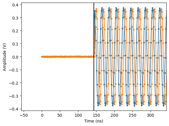
Calibrate TOF#
To ensure proper measurements, we must calibrate the time-of-flight (TOF). This is the time it takes for a signal to travel from the output to the input of the module. To do so, we first play an excitation pulse and acquire it back into
[13]:
prog = """
play    1, 0, 4     # start readout pulse
acquire 2, 0, 16384 # start the 'single' acquisition sequence and wait for the length of the scope acquisition window
stop
"""
[14]:
readout_module.sequencer0.sequence(
    {"waveforms": waveforms, "program": prog, "acquisitions": acquisitions, "weights": {}}
)
[15]:
# Arm and start sequencer.
readout_module.arm_sequencer(0)
readout_module.start_sequencer()

# Wait for the sequencer and acquisition to finish with a timeout period of one minute.
readout_module.get_acquisition_status(0, 1)
readout_module.store_scope_acquisition(0, "single")
# Print status of sequencer.
print(readout_module.get_sequencer_status(0))
Status: STOPPED, Flags: FORCED_STOP, ACQ_SCOPE_DONE_PATH_0, ACQ_SCOPE_DONE_PATH_1, ACQ_BINNING_DONE
c:\work\code\qblox_instruments_install\qblox_instruments\native\generic_func.py:3210: FutureWarning:
        After June 2024, this feature is subject to removal in future releases.
        Transition to an alternative is advised.
        See https://qblox-qblox-instruments.readthedocs-hosted.com/en/main/getting_started/deprecated.html

  warnings.warn(
c:\work\code\qblox_instruments_install\qblox_instruments\native\generic_func.py:2414: FutureWarning:
        After June 2024, this feature is subject to removal in future releases.
        Transition to an alternative is advised.
        See https://qblox-qblox-instruments.readthedocs-hosted.com/en/main/getting_started/deprecated.html

  warnings.warn(
c:\work\code\qblox_instruments_install\qblox_instruments\native\generic_func.py:85: FutureWarning:
            After June 2024, this feature is subject to removal in future releases.
            Transition to an alternative is advised.
            See https://qblox-qblox-instruments.readthedocs-hosted.com/en/main/getting_started/deprecated.html

  self._deprecation_warning()
c:\work\code\qblox_instruments_install\qblox_instruments\native\generic_func.py:77: FutureWarning:
            After June 2024, this feature is subject to removal in future releases.
            Transition to an alternative is advised.
            See https://qblox-qblox-instruments.readthedocs-hosted.com/en/main/getting_started/deprecated.html

  self._deprecation_warning()
c:\work\code\qblox_instruments_install\qblox_instruments\native\generic_func.py:129: FutureWarning:
            After June 2024, this feature is subject to removal in future releases.
            Transition to an alternative is advised.
            See https://qblox-qblox-instruments.readthedocs-hosted.com/en/main/getting_started/deprecated.html

  self._deprecation_warning()
[16]:
p0 = np.array(readout_module.get_acquisitions(0)["single"]["acquisition"]["scope"]["path0"]["data"])
p1 = np.array(readout_module.get_acquisitions(0)["single"]["acquisition"]["scope"]["path1"]["data"])
# Determine when the signal crosses half-max for the first time (in ns)
t_halfmax = np.where(np.abs(p0) > np.max(p0) / 2)[0][0]

# The time it takes for a sine wave to reach its half-max value is (in ns)
correction = 1 / readout_module.sequencer0.nco_freq() * 1e9 / 12

tof_measured = t_halfmax - correction
[17]:
r = readout_module.get_acquisitions(0)["single"]["acquisition"]["scope"]
plt.plot(r["path0"]["data"], ".-")
plt.plot(r["path1"]["data"], ".-")
plt.axvline(tof_measured, c="k")
plt.xlim(
tof_measured - 10 / readout_module.sequencer0.nco_freq() * 1e9,
tof_measured + 10 / readout_module.sequencer0.nco_freq() * 1e9,
)
plt.ylabel("Amplitude (V)")
plt.xlabel("Time (ns)")
plt.show()
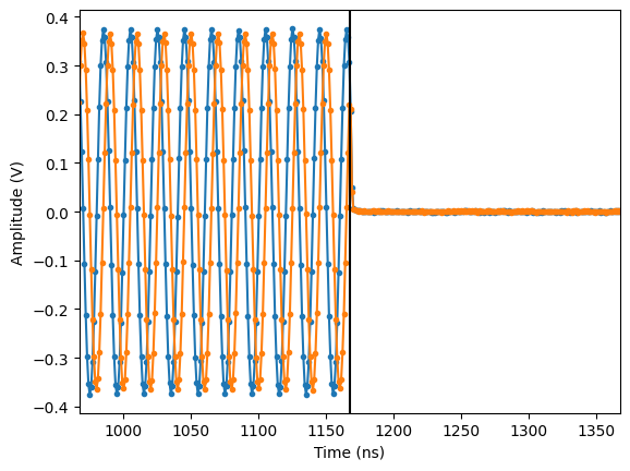
plt.plot(r["path0"]["data"], ".-")
plt.plot(r["path1"]["data"], ".-")
plt.axvline(1024 + tof_measured, c="k")
plt.xlim(
1024 + tof_measured - 10 / readout_module.sequencer0.nco_freq() * 1e9,
1024 + tof_measured + 10 / readout_module.sequencer0.nco_freq() * 1e9,
)
plt.ylabel("Amplitude (V)")
plt.xlabel("Time (ns)")
plt.show()
[18]:
tof = int(tof_measured)  # time of flight must be an integer
print("Measured TOF:", tof_measured)
print("Rounded TOF: ", tof)
Measured TOF: 143.33333333333334
Rounded TOF:  143
Measure qubit histogram#
[19]:
prog = f"""
    move 0, R0
    start: set_mrk 1
    play 2, 3, {tof}
    acquire 0, R0, 120
    play 4, 5, {tof}
    acquire 1, R0, 120
    add R0, 1, R0
    wait 4000
    jlt R0, 1024, @start
    set_mrk 0
    upd_param 4
    stop
"""
[20]:
readout_module.sequencer0.sequence(
    {"waveforms": waveforms, "program": prog, "acquisitions": acquisitions, "weights": {}}
)
[21]:
readout_module.sequencer0.arm_sequencer()
readout_module.sequencer0.start_sequencer()
print(readout_module.sequencer0.get_sequencer_status(1))
Status: STOPPED, Flags: ACQ_SCOPE_DONE_PATH_0, ACQ_SCOPE_DONE_PATH_1, ACQ_BINNING_DONE
[22]:
readout_module.sequencer0.get_acquisition_status(1)
data = readout_module.sequencer0.get_acquisitions()
[23]:
state0 = np.array(data["state0"]["acquisition"]["bins"]["integration"]["path0"]) + 1j * np.array(
    data["state0"]["acquisition"]["bins"]["integration"]["path1"]
)
state1 = np.array(data["state1"]["acquisition"]["bins"]["integration"]["path0"]) + 1j * np.array(
    data["state1"]["acquisition"]["bins"]["integration"]["path1"]
)
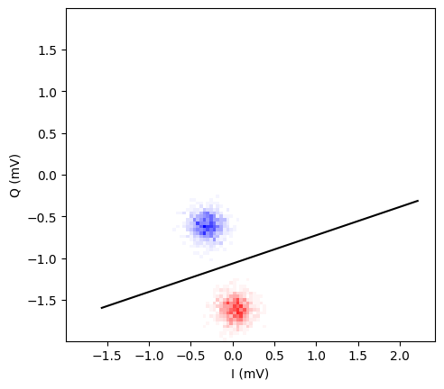
Given this data, we can now determine the rotation and thresholding values to discriminate the \(\left|0\right\rangle\) state from the \(\left|1\right\rangle\) state.
[24]:
rotation = np.mod(-np.angle(np.mean(state1) - np.mean(state0)), 2 * np.pi)
threshold = (np.exp(1j * rotation) * (np.mean(state1) + np.mean(state0))).real / 2
[25]:
scaling = 1000 / integration_length
maxr = max(np.max(np.abs(state0)), np.max(np.abs(state1)))
hist0, xedges, yedges = np.histogram2d(
    state0.real, state0.imag, range=((-maxr, maxr), (-maxr, maxr)), bins=100
)
hist1, xedges, yedges = np.histogram2d(
    state1.real, state1.imag, range=((-maxr, maxr), (-maxr, maxr)), bins=100
)

plt.imshow(
    1 - np.array((hist0, hist0 + hist1, hist1)).transpose(2, 1, 0) / np.max(hist0 + hist1),
    extent=(-maxr * scaling, maxr * scaling, -maxr * scaling, maxr * scaling),
    origin="lower",
)
plt.plot(
    ((1j * xedges + threshold) * np.exp(-1j * rotation)).real * scaling,
    ((1j * xedges + threshold) * np.exp(-1j * rotation)).imag * scaling,
    "k",
)
plt.xlabel("I (mV)")
plt.ylabel("Q (mV)")
plt.show()
[26]:
readout_module.sequencer0.thresholded_acq_threshold(threshold)
readout_module.sequencer0.thresholded_acq_rotation(rotation * 360 / (2 * np.pi))
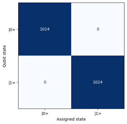
Now that the rotation and thresholding values are programmed into the QRM module, the module will automatically assign a qubit state to every acquisition. By running the same sequence as before, we can check the the module is assigning the correct state to the qubit.
[27]:
readout_module.sequencer0.delete_acquisition_data(all=True)
readout_module.sequencer0.arm_sequencer()
readout_module.sequencer0.start_sequencer()
print(readout_module.sequencer0.get_sequencer_status(1))
Status: STOPPED, Flags: ACQ_SCOPE_DONE_PATH_0, ACQ_SCOPE_DONE_PATH_1, ACQ_BINNING_DONE
[28]:
readout_module.sequencer0.get_acquisition_status(1)
data = readout_module.sequencer0.get_acquisitions()
To check that the assignments are made correctly, we calculate the confusion matrix.
[29]:
confusion_matrix = [
    [
        np.sum(np.array(data["state0"]["acquisition"]["bins"]["threshold"]) == 0),
        np.sum(np.array(data["state0"]["acquisition"]["bins"]["threshold"]) == 1),
    ],
    [
        np.sum(np.array(data["state1"]["acquisition"]["bins"]["threshold"]) == 0),
        np.sum(np.array(data["state1"]["acquisition"]["bins"]["threshold"]) == 1),
    ],
]
[30]:
p = plt.matshow(confusion_matrix, cmap="Blues", vmin=0, vmax=1024)
ax = plt.gca()
for i in [0, 1]:
    for j in [0, 1]:
        ax.annotate(
            confusion_matrix[i][j],
            xy=(j, i),
            horizontalalignment="center",
            verticalalignment="center",
            color=p.cmap(1024 - confusion_matrix[i][j]),
        )
plt.xlabel("Assigned state")
plt.ylabel("Qubit state")
plt.xticks([0, 1], ["|0>", "|1>"])
plt.yticks([0, 1], ["|0>", "|1>"])
ax.xaxis.set_ticks_position("bottom")
plt.show()
Sending results on the trigger network#
Now that the module can correctly identify the qubit state, we want to send this result to all other modules in the Cluster. Hence we must enable this functionality and specify an address used for sending these triggers. In this tutorial, we will only use address 1. Note that only one trigger can be sent simultaneously, even if the address is different.
[31]:
readout_module.sequencer0.thresholded_acq_trigger_address(1)
readout_module.sequencer0.thresholded_acq_trigger_en(True)
To verify that the correct triggers are being sent, we can use the trigger monitor. This monitor can be reset with the following command:
[32]:
cluster.reset_trigger_monitor_count(address=1)
Such that the monitor reports both a total trigger count of 0 and no latest trigger (also represented by the value 0)
[33]:
cluster.trigger1_monitor_count(), cluster.trigger_monitor_latest()
[33]:
(0, 0)
Now, to verify the Cluster is configured correctly, let us run the above program one more time:
[34]:
readout_module.sequencer0.delete_acquisition_data(all=True)
readout_module.sequencer0.arm_sequencer()
readout_module.sequencer0.start_sequencer()
readout_module.sequencer0.get_sequencer_status(1)
readout_module.sequencer0.get_acquisition_status(1)
data = readout_module.sequencer0.get_acquisitions()
The number of triggers received by the monitor should be equal to the number of measurements that have been classified as the \(\left|1\right\rangle\) state.
[35]:
print(
    "Acquisition:",
    np.sum(np.array(data["state0"]["acquisition"]["bins"]["threshold"]) == 1)
    + np.sum(np.array(data["state1"]["acquisition"]["bins"]["threshold"]) == 1),
)
print("Monitor:    ", cluster.trigger1_monitor_count())
Acquisition: 1024
Monitor:     1024
The most recent trigger that has been received should now be equal to 1.
[36]:
cluster.trigger_monitor_latest()
[36]:
1
Besides investigating the sent triggers using this monitor, it can be convenient to visualize the triggers on an oscilloscope as they are being sent. In order the enable sending the trigger on marker 4, use the following commands. Enabling triggers on the marker outputs can also be used to control external equipment based on the measurement results.
[37]:
readout_module.sequencer0.thresholded_acq_marker_en(True)
readout_module.sequencer0.thresholded_acq_marker_address(8)
Now connect your marker output 4 to the oscilloscope and run the following cell.
[38]:
readout_module.sequencer0.arm_sequencer()
readout_module.sequencer0.start_sequencer()
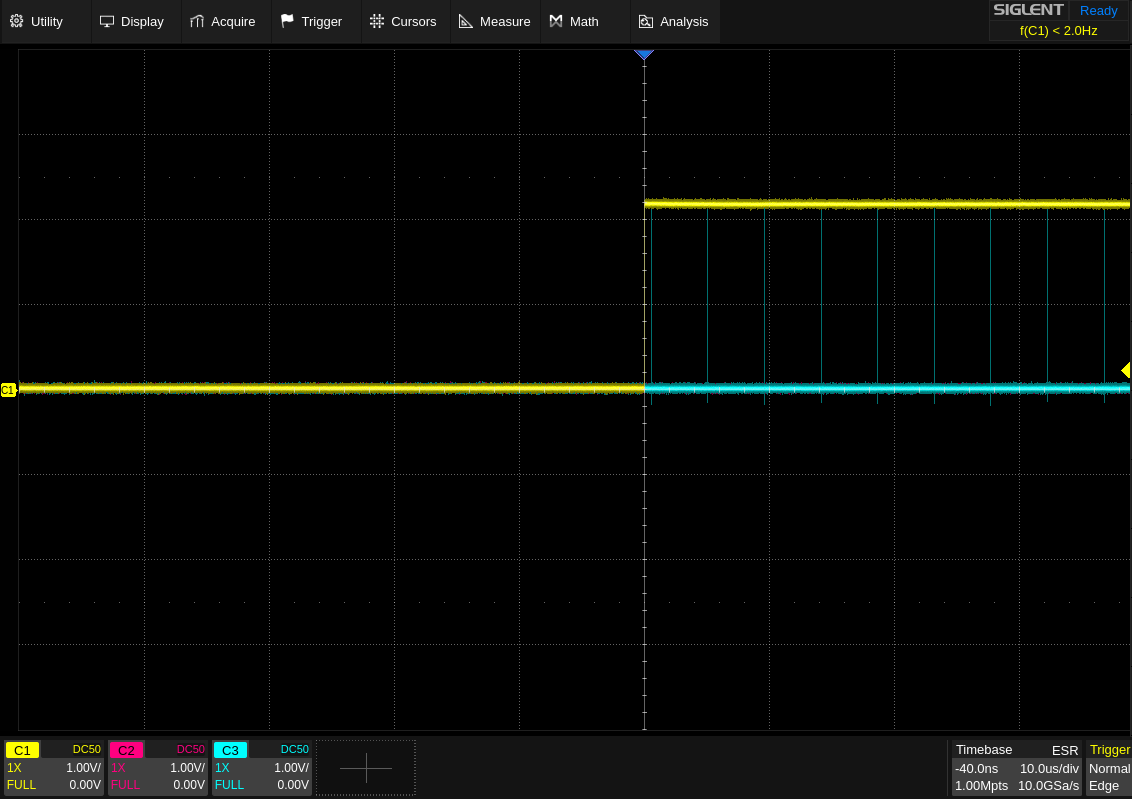
The following image can be obtained on the oscilloscope (C1 (yellow) is the marker 1 output whereas C3(blue) is marker 4 output:
Active reset#
As the final part of this tutorial, we will show how the triggers we have been generating above, can be used to affect the behavior of other sequencers in the Cluster. We will show this capability using a active reset protocol as an example. Basically, in order to perform active reset on a qubit, we must first measure the qubit state, and if the state equals \(\left|1\right\rangle\), we must play a \(\pi\)-pulse to flip the qubit back to the \(\left|0\right\rangle\) state.
In a real qubit setup, the QRM would play identical readout pulses and the actual qubit state would influence the acquisition result. For this tutorial, in lieu of a qubit, we determine the qubit state results in advance for the QRM, and play a different waveform depending on this pre-determined state. To still properly demonstrate the feedback capability, we ensure that the QCM is not aware of the pre-determined choices in advance, as it can figure out from the acquisitions results whether it should play a \(\pi\)-pulse.
Generate 100 random qubit states:
[39]:
length = 100
states = np.random.choice(2, length)
states
[39]:
array([1, 1, 1, 0, 0, 0, 0, 1, 1, 0, 1, 0, 0, 1, 0, 1, 1, 0, 1, 0, 1, 0,
       0, 1, 0, 0, 0, 0, 1, 1, 1, 1, 1, 1, 1, 1, 0, 0, 0, 1, 0, 0, 0, 1,
       1, 0, 0, 1, 1, 1, 0, 1, 1, 0, 1, 1, 1, 0, 1, 0, 1, 0, 1, 1, 0, 0,
       0, 0, 1, 0, 0, 0, 0, 0, 0, 1, 1, 1, 0, 0, 1, 0, 0, 1, 1, 1, 1, 1,
       1, 1, 1, 0, 0, 0, 0, 1, 0, 0, 1, 1])
For the QRM program, this means playing waveforms 'state0_I' and 'state0_Q' if the qubit state has to appear as \(\left|0\right\rangle\) while playing waveforms 'state1_I' and 'state1_Q' if the qubit state has to appear as \(\left|1\right\rangle\).
[40]:
qrm_prog = """
wait_sync 4
set_mrk 1
upd_param 1000
move 0, R0
"""
for s in states:
    if s == 1:
        qrm_prog += f"""set_mrk 3
        play 4, 5, {tof}
        set_mrk 1"""
    else:
        qrm_prog += f"play 2, 3, {tof}"
    qrm_prog += """
    acquire 0, R0, 120
    wait 1000
    """
qrm_prog += """set_mrk 0
upd_param 1000
stop"""
So, in order to achieve feedback from the QRM module, we only had to set the thresholding and trigger parameters without any changes to the Q1ASM program. On the receiving side, for the QCM, the feedback is controlled via Q1ASM, however. Let’s build up the program step by step.
First, we need to tell the module to listen for triggers on address 1 with:
[41]:
qcm_prog = "set_latch_en 1, 4 # Enabling listening to triggers on address 1"
We can then sync with the other module and program our loop:
[42]:
qcm_prog += f"""
wait_sync 4
wait 1000
move {len(states)}, R0
s:
"""
# Here we need to write the code to receive and react to triggers
# Therefore, we store then end of the program in a separate variable for now
qcm_prog_tail = """
loop R0, @s
stop
"""
For every iteration of our loop, we first need to clear any received triggers and then wait for any new trigger to come in:
[43]:
qcm_prog += f"""
latch_rst {tof+120}   # Deletes all previously received triggers
wait      300         # gives the acquisition result time to be received by the QCM
"""
Next, we program a conditional play instruction. In order to mark a play, acquire, acquire_weighed or wait instruction as conditional, we open a conditionality block using the set_cond <enable> <address_mask> <operator> <else_wait> instruction.
The <enable> argument sets whether subsequent real-time pipeline instructions are conditional or not. In case a conditional instruction is skipped, the <else_wait> argument determines how long the real-time pipeline will stall (minimum is 4 ns).
The <address_mask> and <operator> determine the conditionality, if the condition evaluates to True the instruction es executed, otherwise the instruction will be skipped (equivalent to a wait <else_wait> instruction).
When only listening to a single trigger address, the <address mask> should be made equal to 2**(address-1) and the <operator> should be 0 for OR or 2 for AND (both having the same effect for a single input, feedback based on multiple trigger addresses is not covered in this tutorial). To invert the conditional, <operator> 1 for NOR or 3 for NAND can be used.
For active reset, we can enable the conditional with:
[44]:
qcm_prog += """
set_cond 1, 1, 0, 700 # Enable conditional commands
"""
Next we can invoke our play command as usual:
[45]:
qcm_prog += "play 6, 7, 700"
Finally, do not forget to disable the conditional commands again (after the first 0, the parameters do not matter):
[46]:
qcm_prog += (
    """
set_cond 0, 1, 0, 700 # Disable conditional commands again
"""
    + qcm_prog_tail
)
In summary, the complete QCM program is:
[47]:
print(qcm_prog)
set_latch_en 1, 4     # Enabling listening to triggers on address 1
wait_sync 4
wait 1000
move 100, R0
s:

latch_rst 263   # Deletes all previously received triggers
wait      300         # gives the acquisition result time to be received by the QCM

set_cond 1, 1, 0, 700 # Enable conditional commands
play 6, 7, 700
set_cond 0, 1, 0, 700 # Disable conditional commands again

loop R0, @s
stop
[48]:
control_module.sequencer1.sync_en(True)  # We did not enable the sync on the QCM sequencer yet

readout_module.sequencer0.sequence(
    {"waveforms": waveforms, "program": qrm_prog, "acquisitions": acquisitions, "weights": {}}
)
readout_module.sequencer0.arm_sequencer()

control_module.sequencer1.sequence(
    {"waveforms": waveforms, "program": qcm_prog, "acquisitions": acquisitions, "weights": {}}
)
control_module.sequencer1.arm_sequencer()
We are all set to witness the conditional playback! Please make sure that you have connected the QCM output 0 to the oscilloscope along with the marker 1 of QRM as trigger and marker 4.
[49]:
readout_module.start_sequencer()
control_module.start_sequencer()
[50]:
print("QRM:")
print(readout_module.get_sequencer_status(0, 1))
print("QCM:")
print(control_module.get_sequencer_status(0, 1))
QRM:
Status: STOPPED, Flags: ACQ_SCOPE_DONE_PATH_0, ACQ_SCOPE_DONE_PATH_1, ACQ_BINNING_DONE
QCM:
Status: STOPPED, Flags: NONE
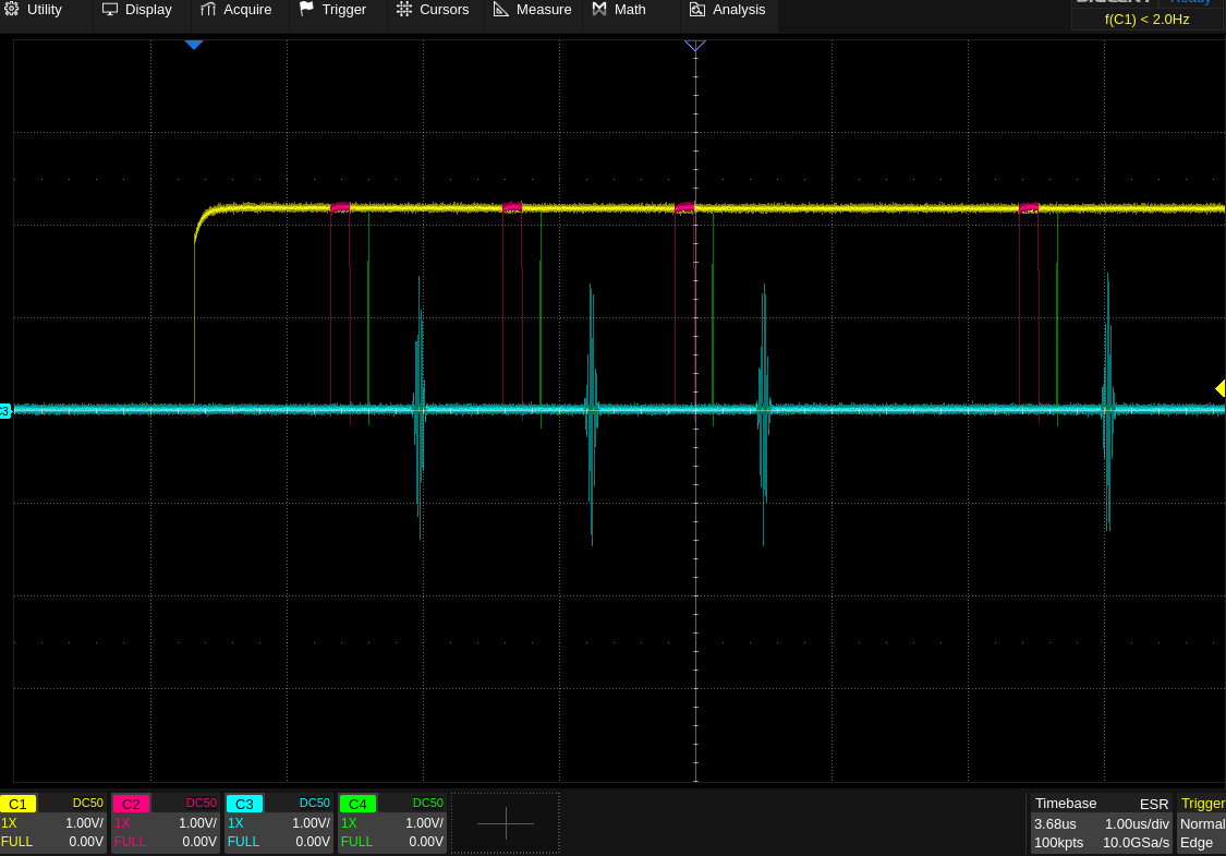
On the oscilloscope, you should see an image as below (CH1 (yellow) : Marker 1, CH2 (pink): Marker 2, CH3(blue) : QCM Output 0, CH4(green) : Marker 4). Marker 2 activation corresponds to a state 1 signal by QRM which is confirmed by the Marker 4
Stop#
[51]:
# Stop sequencers.
control_module.stop_sequencer()
readout_module.stop_sequencer()

# Print status of sequencers.
print("QCM :")
print(control_module.get_sequencer_status(0))
print()

print("QRM :")
print(readout_module.get_sequencer_status(0))
print()

# Reset the cluster
cluster.reset()
print(cluster.get_system_status())
QCM :
Status: STOPPED, Flags: NONE

QRM :
Status: STOPPED, Flags: FORCED_STOP, ACQ_SCOPE_DONE_PATH_0, ACQ_SCOPE_DONE_PATH_1, ACQ_BINNING_DONE

Status: OKAY, Flags: NONE, Slot flags: NONE
c:\work\code\qblox_instruments_install\qblox_instruments\native\generic_func.py:1033: FutureWarning:
        After June 2024, this feature is subject to removal in future releases.
        Transition to an alternative is advised.
        See https://qblox-qblox-instruments.readthedocs-hosted.com/en/main/getting_started/deprecated.html

  warnings.warn(