QTM#
Description#
The Qubit Timetagging Module (QTM) is Qblox’s solution for timetagging and counting of photodetector signals, in order to perform qubit readout in optical qubit systems. The QTM enhances the digital signal generation and acquisition, including time acquisition to the cluster. The module has 8 SMP channels, that can be configured to act as inputs or outputs. The front of a QTM module is presented below:
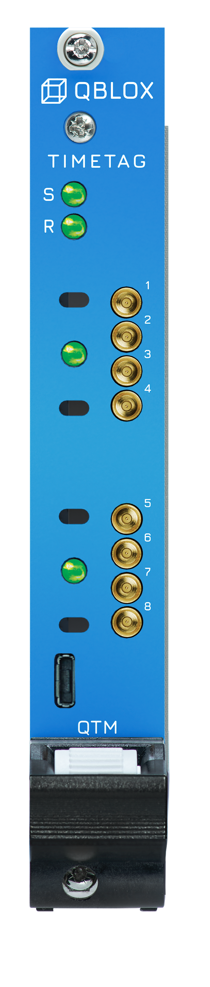
On the front of a QTM module you will find the following components:
8 x SMP male (pin) connectors: Data Input/Output (DIO) (0-3.3 V TTL).
4 x status LEDs: 1 LED per Quad (4 I/O ports). See section Frontpanel LEDs for details.
For dynamic operation, each channel has a dedicated Q1 sequencer (see here for more information Q1 Sequence Processor). The QTM allows feedback based on photodetector counts.
The input path features rising edge detection, allowing for precise detection of analog signals. The threshold voltage for this detection can be finely adjusted using a`Qcodes` parameter IOChannel.in_threshold_primary(). Events corresponding to the rising edges can be timestamped to a single-shot accuracy as fine as 20 picoseconds.
Two acquisition modes are available: scope mode and binning mode, both be can be done simultaneously. In scope mode, you can perform a timetag trace acquisition where up to 2048 time tags can be stored, capturing a detailed snapshot of the input signal. Conversely, the binning mode allows one to capture one time delta per acquisition window, which is the difference between one timetag and a reference time.
The module includes a counting feature, which tallies the occurrences of rising edge events.
Input gating or windowing can be applied via the Q1 sequencer. This capability allows for precise selection of signal segments.
The output signal is a TTL into high impedance and half TTL level when 50 ohm terminated. The digital pulses can be placed arbitrarily on a 39 ps stepgrid.
For a list of available features please go to Features.
Block Diagram#

Features#
1. 10MHz Reference#
Alongside all modules available, the QTM module operates with respect to a 10MHz reference provided by the cluster.
2. Trigger#
The trigger of the QTM is connected to the cluster and allows for fast synchronization between modules.
3. SYNQ#
The Qblox SYNQ technology enables simple and quick synchronization over multiple instruments, allowing for modules to be started synchronously << 1ns. See section Synchronization for more information.
4. LINQ#
The Qblox LINQ technology allows for the results of measurements to be shared between devices, distributing outcomes in < 364ns.
5. Q1 Sequencers#
The Q1 sequencers are the heart(s) of the QTM instrument. They orchestrate the experiments using a custom low-latency sequence processor specifically designed for quantum experiments. There are eight sequencers in total in a QTM module.
The acquire_timetags command allows users to control the window where the acquisitons will be counted, the fine_delay parameter effectively delays the acquire_timetags command in steps of 39 picoseconds, without affecting instruction timing or timing of the rest of the sequencer. It can be thought of as subtracting from the time-of-flight delay of the incoming signal, and can therefore be used to do fine calibrations of this delay at runtime, without having to affect sequencer instruction timing. The adjustment range is 16 nanoseconds, with a command resolution of 1/128ns. You can see the Q1asm parameters specific to the QTM in this table here.
6. Sequencer Channel Mapping#
By default each channel is controlled and monitored by exactly 0 or 1 sequencers (if 0, static control of the output is still possible via QCodeS parameters). A single sequencer can be configured to control all channels.
In this default setup, all channels are independent and can independently be configured to be inputs or outputs. A single sequencer can control a single acquisition window, via acquire_timetags. Therefore, if independent windows are needed for an application, the user must use independent sequencers. It is also possible to acquire the same signal with two sequencers via the fan-out channel combine mode. In this mode, the analog input signal of the main channel in a pair is routed to the input circuitry of both the main and auxiliary channel, allowing different sequencers to be used for either, and thus allowing for two different, potentially overlapping acquisition windows.
7. Digital Output#
In output mode, a DIO channel electrically behaves like a marker. However, QTM outputs support more fine-grained control than markers. Rather than extending the capabilities of the Q1asm set_mrk which is used to control marker outputs for the QxM modules, set_digital is now used to control whether the digital output is set to high or low.
Fine-grained timing control is possible with the addition of a fine delay parameter. This parameter can be used to delay the output command up to 16ns in 39ps steps. Using this, it’s possible to delay the leading edge to make pulses shorter than the sequencer would otherwise allow, it’s possible to shift the output with respect to the 1ns timegrid which the cluster operates on for fine time of flight compensation or calibration.
8. Settable Analog threshold#
When acquiring the signal is first digitized by means of an analog threshold operation, the voltage of which is QCoDeS-configurable.
9. Digital Input#
Regardless of whether a DIO channel is in input or output mode, the signal at the connector is compared against the analog threshold voltage IOChannel.in_threshold_primary(). After this, two types of acquisitions are performed: 1GSPS sampling and timetagging (via a Time-to-Digital Converter aka TDC). These modes are always available in parallel.
1GSPS - The 1GSPS sampling logic allows a scope acquisition enabled with the set_scope_en Q1asm instruction, and level acquisitions triggered by acquire_digital Q1asm instruction.
TDC - The timetagging logic is capable of detecting a rising edge with a precision of 20 ps RMS. Using the Q1asm instruction acquire_timetags, binning and averaging of rising edge counts can be performed, as well as the binned acquisition of a time delta per acquisition window, i.e. the difference between a recorded rising edge and a reference time defined by the user. It also allows a trace acquisition where up to 2048 timetags can be recorded, triggered by acquire_timetags. The user can select whether all timetags are recorded, or only those that fall within a acquire_timetags window. In the latter case, the window open and close times are also recorded. Aditionally, in trace mode the timetags are recorded based on an absolute time.
Applications#
The Qubit Timetag module (QTM) is primarily designed to be utilized for photon counting by connecting the module to photon detectors. The fine time-controlled windowing capability of the QTM allows accurate photon counting which in certain type of qubit system relates to the the quantum state of the qubit.
Specifications#
Specifications QTM |
|
|---|---|
Digital input/output channels |
8 I/0 |
Output voltage |
3.3 V TTL (in 66 Ohm) |
Output rate |
1 GS/s |
Output skew resolution |
39 ps |
Input threshold voltage |
0 - 5V (11 bit) |
Input resolution TDC |
20 ps (RMS) |
Dead time TDC |
44 ns |
Repetition rate |
22 MHz |
Timetag trace memory |
2048 timetags |
Timetag memory |
131.072 timetags |
Count result memory |
131.072 bins |
Maximum no. of counts per bin |
4e9 |
Ethernet data rate |
1 Gbit/s |
Driver/API |
SCPI / Python/QCoDeS |
Max. power consumption via Cluster |
48 W |
Input/Output connector type |
SMP |
Dimensions |
269 x 130 x 20 mm3 |
Weight |
0.356 kg |