Mainframe & CMM#
Description#
In this section, we have a look at the Qblox Cluster mainframe and the Cluster management module (CMM) and their I/O.
Mainframe Front#
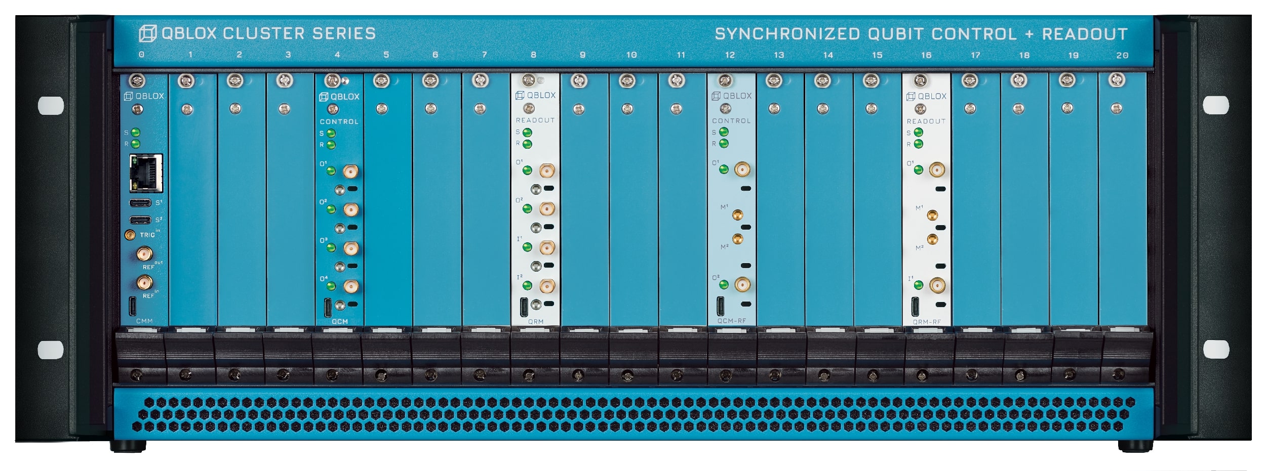
CMM module: present in every Cluster in slot 0, it allows communication from and to the host PC via Ethernet and the other modules. See more below.
20x module slots: each can be occupied by any module among QCM, QCM-RF, QRM, QRM-RF or it can be left unoccupied. New modules can be added at any time when the cluster is switched off as the quantum device scales.
Mainframe Back#
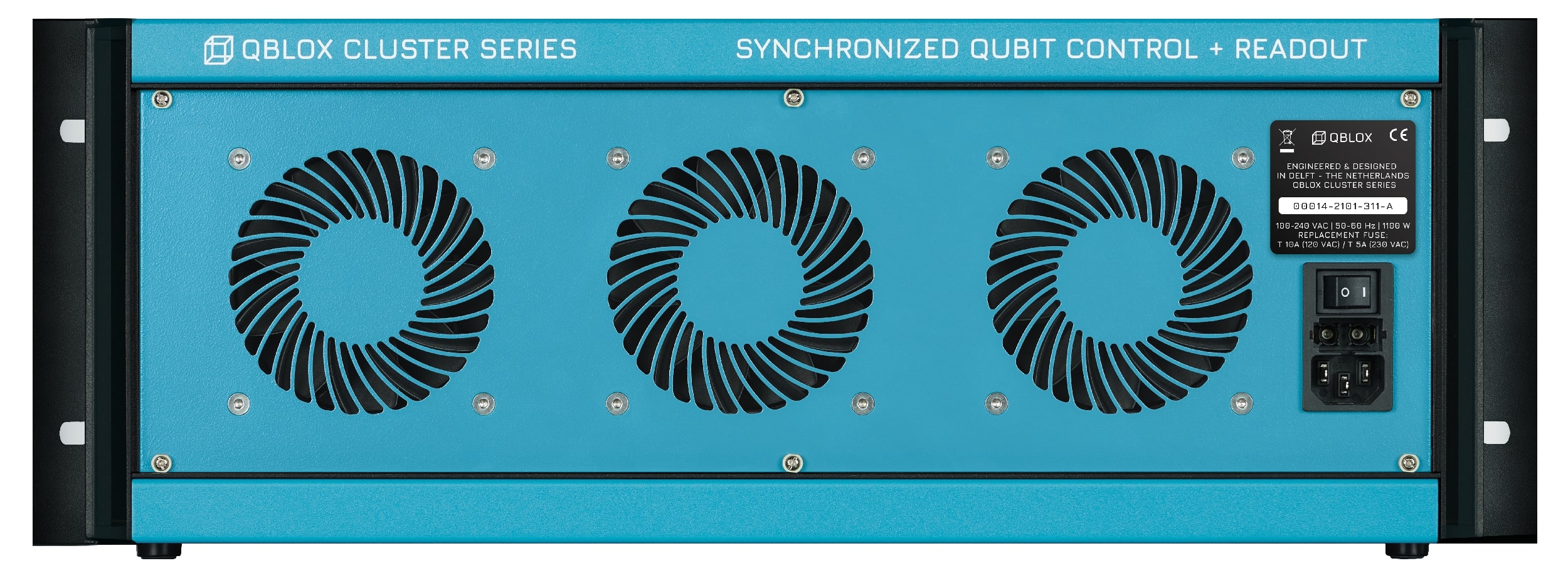
Power supply: 100-240 VAC, 50-60 Hz, 1100W.
Switch on/off.
3x cooling fans with dynamic fan control to minimize noise and keep a stable internal temperature.
CMM module#
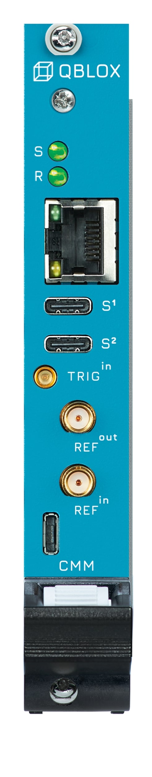
2x status LEDs: See section Frontpanel LEDs for details.
RJ45: 1 Gbps Ethernet host PC connection.
2x USB-C:
—2x SYNQ: For synchronizing modules in multiple Qblox instruments.
1x USB-micro:
—UART/JTAG: For debug purposes only.
2x SMA:
—REF\(^\mathrm{\mathbf{in}}\) External 10 MHz reference clock input (1 Vpp nominal @ 50 Ω).
—REF\(^\mathrm{\mathbf{out}}\) 10 MHz reference clock output (0-3.3 V @ 50 Ω).
1x SMP:
—TRIG\(^\mathrm{\mathbf{in}}\) External trigger input (0-3.3 V, high-Z).
Block Diagram#

Features#
1. Modularity#
The Cluster is an all-inclusive 19” rack instrument taking up 4 units (4u) of rack space that can be configured with a combination of up to 20 modules for qubit control and readout. This allows for up to 80 channels + 80 marker outputs per Cluster. Each module can be chosen either among the baseband line (0-400 MHz) or RF line (2-18.5 GHz), each for either control (QCM, QCM-RF) or readout (QRM, QRM-RF). Thanks to its versatile modularity, the Cluster can adapt and scale along with the experimental needs and number of qubits in the quantum device under test.
2. Full integration#
Within a single 19” rack the Cluster integrates lots of AWGs, local oscillators, analyzers, IQ-mixers, and digitizers, allowing for direct signal generation and acquisition with frequencies up to 18.5 GHz. Our proprietary SYNQ and LINQ backplane protocols (see below) ensure that all the modules in the Cluster act together as a solid, massively-scalable system.
3. SYNQ#
The SYNQ protocol organizes a synchronized start of the sequencers to ensure fully deterministic, fixed-timing relations between all the modules in the Cluster. It synchronizes all analog and digital channels mounted in a Cluster down to picoseconds level. This extends to multiple Clusters as well by daisy chaining them with SYNQ interconnects.
See section Synchronization for more information.
4. Scalable Feedback with LINQ#
Our proprietary LINQ protocol allows for low-latency feedback with an arbitrary control flow by distributing measurement outcomes to all modules in less than 320 ns. This all-to-all connectivity allows for applying conditionally generated pulses based on the result of a measurement from any other module.
5. Backplane#
The Cluster backplane stands as the backbone of our proprietary SYNQ to assure synchronization among all the channels and of the LINQ protocol for low-latency feedback with all-to-all connectivity. The backplane also hosts a 10 MHz reference clock. External clocks or triggers can also be sent via the backplane in cases where other electronics are used as a master clock.
6. Ready for quantum error correction with real-time decoding#
The all-to-all connectivity enabled by the LINQ protocol is scalable to multiple Clusters to allow for quantum error correction on a >1000 qubits system. Even extensions with dedicated modules for computationally demanding tasks like real-time error decoding are within reach.
7. Scale up to 100s of qubits with Multi-Cluster control stacks#
The Cluster protocols SYNQ and LINQ enable scalable control of 100s of qubits while maintaining synchronicity and arbitrary control flow with low-latency feedback.
Operation#
Control#
All Qblox instruments, excluding the SPI Rack, are controlled over Ethernet. All Qblox instruments use a Python driver based on QCoDeS. We recommend using this driver as it provides easy and clear access to all functionality of the instrument; even if you use a different lab framework as the overhead of QCoDeS is minimal.
Underneath the QCoDeS driver layer, the control software is built upon the SCPI standard, as also reflected in API Reference.
This means that all communication with the instrument happens using the master/slave paradigm, where the host PC is the master and is always responsible for initiating communication by
issuing SCPI commands to the instrument. Of course, all of this is abstracted away at the driver level, so you don’t have to have in-depth knowledge of the standard. However, if you are familiar
with it, you will have access to all the default SCPI functionality that you are used to, like get_idn() (*IDN?), reset() (*RST) and
clear() (*CLS), albeit with a slightly more readable name.
Reset#
We advise resetting the instrument before starting your experiment to get the instrument into a well-defined state, thereby improving the reproducibility of the experiment. Resetting the
instrument is easily achieved by calling reset(). This will reset the instrument status and configuration to the default values. It will reset all SCPI registers, including
any reported error. It will also clear all stored Q1ASM programs, waveforms, and acquisitions.
There are many use cases where you want to store the instrument’s settings before resetting, for instance, to be able to easily reproduce an experiment. For this, we advise using the snapshot feature of QCoDeS.
Errors#
Instrument errors are reported using SCPI’s system error registers, which can be read using get_num_system_error() (SYSTem:ERRor:COUNt?) and
get_system_error() (SYSTem:ERRor:NEXT?). However, as mentioned before, this is all abstracted away at the driver level. This means that the errors are automatically read
and reported to you using exceptions. Any driver function can throw these exceptions and you need to make sure these are handled appropriately, for instance by using
try statements.
Status#
The status of the instrument conveys the general operational condition of the instrument.
This is derived from multiple internal components, like PLLs and temperature sensors.
The instrument’s status is updated every millisecond and stored in the standard SCPI registers.
It can be queried through these registers [e.g. through
get_status_byte() (*STB?)],
but a more convenient way of reading out the general instrument status is calling
get_system_state().
This returns the following status and accompanying flags that elaborate on the status:
Status:
BOOTING: Instrument is booting.OKAY: Instrument is operational.CRITICAL: Instrument has encountered an error (see flags below), but it has been corrected.ERROR: Instrument has encountered an error (see flags below), which needs to be fixed urgently.
Flags:
CARRIER PLL UNLOCKED: No reference clock found.FPGA PLL UNLOCKED: No reference clock found.LO PLL UNLOCKED: No reference clock found (only for RF modules).FPGA TEMPERATURE OUT-OF-RANGE: FPGA temperature has surpassed 80°C.CARRIER TEMPERATURE OUT-OF-RANGE: Carrier board temperature has surpassed 100°C.AFE TEMPERATURE OUT-OF-RANGE: Analog frontend board temperature has surpassed 100°C.LO TEMPERATURE OUT-OF-RANGE: Local oscillator board temperature has surpassed 100°C.BACKPLANE TEMPERATURE OUT-OF-RANGE: Backplane board temperature has surpassed 100°C (only for Cluster).
The instrument status is persistent through the state critical, so a way to reset it is required. This can be simply done by calling the clear() to clear the state or by
completely resetting the instrument by calling reset().
Frontpanel LEDs#
The LEDs on the front panel of the Qblox instruments are used as a visual indication of the status of the instrument. The LED colors indicate the following status:
S |
White |
Okay and idle (no connections). |
Green |
Okay. |
|
Yellow |
Booting (other LEDs are off). |
|
Orange |
Critical. |
|
Red |
Error. |
|
R |
Green |
External reference clock selected. |
Blue |
Internal reference clock selected |
|
Red |
No reference clock found. |
|
I/O |
Green |
Channel idle. |
Purple |
Sequencer connected to channel is armed. |
|
Blue |
Sequencer connected to channel is running. |
|
Red |
Sequencer connected to channel failed. |
|
Orange |
Output values are clipping. |
It’s also possible for all LEDs to show a combination of red and purple. On older firmware versions, this happens naturally while the device is rebooting, but otherwise, you’ve stumbled onto a firmware bug! If you’re not already using the latest firmware, please update your device. If the problem persists, please contact us.
Tools#
Configuration management#
The configuration manager allows you to manage Cluster instruments from within Python. It comes in the form of a Python API (Configuration management) as well as a command line tool (qblox-cfg). In the environment where you have installed qblox-instruments, simply run qblox-cfg --help and a list of available commands will follow. Run qblox-cfg <command> help for more information about a command.
Plug & Play#
Qblox Plug & Play allows you to scan your LAN for instruments from Qblox. It also comes in the form of a Python API (Plug & Play) as well as a command line tool (qblox-pnp). In the environment where you have installed qblox-instruments, simply run qblox-pnp --help and a list of available commands will follow. Run qblox-pnp <command> help for more information about a command.
Absolute Maximum Ratings#
Warning
This section shows the absolute maximum ratings of the cluster. Operation beyond these values can damage the cluster and installed modules!
Intended use#
The devices are meant for indoor use in an office or laboratory environment only.
For questions or more details, please contact us here.
Maximum ratings#
Parameter |
Condition |
Min |
Typ |
Max |
|---|---|---|---|---|
Rated AC voltage |
90V |
265V |
||
Rated AC frequency |
47Hz |
50/60Hz |
63Hz |
|
Trigger input voltage range |
0.0V |
3.3V |
||
Reference input voltage range |
-4.4V | | 4.4V |
|||
Environmental#
Parameter |
Min |
Max |
|---|---|---|
Temperature |
5°C |
40°C |
Relative Humidity |
80% |
|
Altitude |
2000m |
|
Operating Environment |
IEC6101-1 |
|
Indoor location |
||
Pollution degree 2 |
||
Overvoltage category II |
||
Specifications#
Power Rating#
Parameter |
Condition |
Min |
Typ |
Max |
|---|---|---|---|---|
Rated AC voltage |
90V |
265V |
||
Rated AC current |
Vin = 90Vac |
13.6A |
||
Rated AC frequency |
47Hz |
50/60Hz |
63Hz |
|
Rated power |
1100W |
|||
Fuse |
Vin=120Vac |
10A, Time delayed |
||
Fuse |
Vin=230Vac |
5A, Time delayed |
||
Note
For voltages between 110 Volt and 230 Volt, the fuse rating can be linearly interpolated.
Digital Interface#
Parameter |
Description |
|---|---|
Host computer connection |
1 GbE, Lan/Ethernet, 1Gbit/s. |
SYNC port |
Connector for Qblox proprietary synchronization protocol over a USB-C type connector. |
The ethernet should always be connected with a shielded category 5 or 6 ethernet cable. For optimal performance, use the included Cat6 S/FTP cables or similar ones.
I/O#
Parameter |
Condition |
Min |
Typ |
Max |
|---|---|---|---|---|
External clock input impedance |
50Ω |
|||
External clock input frequency |
10MHz |
|||
Reference clock output impedance |
50Ω |
|||
Reference clock output amplitude |
High impedance load |
3.3V |
||
Reference clock output frequency |
10MHz |
|||
Trigger input impedance |
100k |
|||
Trigger input voltage range |
0.0V |
3.3V |
||
Trigger input threshold level |
0.9V |
Dimensions#
Parameter |
Condition |
Min |
Typ |
Max |
|---|---|---|---|---|
Dimensions |
W x H x D |
482 x 176 x 474 mm |
||
19 x 6.9 x 18.7 inch |
||||
Weight |
Empty Rack |
9.35 kg |
||